Highway to the TrustZone (Using Rust with TrustZone-M)
This post is kind of a long ramble, and the goal is to take people from 0 to semi-productive with TrustZone-M. That means that we'll go over a bunch of background on enclaves, embedded devices, and the Rust embedded scene. If you just want to get to the meat and potatoes of how to use TrustZone-M with Rust, feel free to just checkout our bootloader framework Frumsceaft.
So you've decided you want to use ARM TrustZone huh.
If you are anything like me you'll have vaguely heard of ARM TrustZone, and maybe even googled a little bit about it. Before diving into this project I had assumed it was roughly equivalent to Intel's SGX, which I had experience with. Both TrustZone and SGX are examples of trusted execution environments or enclaves, features of modern CPUs that allow for "secure" execution of code.
A brief prelude, to describe Intel SGX
AKA "But what does secure actually mean?"
Each TEE solution defines their security guarenetees a little differently. Intel SGX can appear pretty intimidating, but it really just provides three broad features: memory protection, attestation, and sealing. Now let's quickly unpack each of those. Memory protection means that no process, not even the kernel, can access the memory of the enclave. This is a feature enforced by the CPU itself, so it should work just fine.
Ignoring that SGX had a vulnerability where you could read the first few bytes of a cache line. Forcing us paranoid engineers to pad our secrets.
Attestation is one of the biggest selling points of enclaves. It allows you to prove that the code running in an enclave is signed by a certain key and that it is running in an enclave. Intel does this by generating a unique key per CPU in the factory, and somehow installing it into the CPU. The CPU can then generate reports signed with that key, which can then be verified at a centralized Intel database of valid keys. Now if this sounds a little insecure, it's because it is. There is a massive single point of failure here, that central database of keys. Unfortunately, in this case, that's just the way cookie crumbles.
Ok this is a little bit of simplification. SGX has multiple modes attesation, and uses something called EPIDs for the actual attesation process.
Lastly, sealing. Sealing allows you to encrypt data so it can only be decrypted by authorized code. For Intel SGX that is code on a particular CPU, and signed by a particular developer.
TrustZones plural
Okay! I just spent the last minute of your precious time describing a different technology than the one in the title of the blog post, what gives? Well, it is good to vaguely understand an enclave solution before we discuss TrustZone. So what is TrustZone? Confusingly it's whatever ARM marketing wants it to be.
Much like VMWare before them, ARM has named at least two separate technologies "TrustZone". There is TrustZone-A which runs on their higher power Cortex-A processors. There is likely a Cortex-A processor in your phone, or maybe even in the computer, you are reading this on. TrustZone-A is a product similar to Intel SGX, and won't be the topic of discussion today. If at some point someone convinces me to use TrustZone-A, I'm sure to have a similar explainer (unfiltered rant) planned. TrustZone-M runs on Cortex-M processors. These are low-power microcontrollers that have limited features in comparison to Cortex-A CPUs. They are all 32bit, and importantly lack MMUs (Memory management Units). That means all of that fancy virtual-memory mumbo-jumbo you soft-bellied Linux embedded developers are used to is out of the window. Instead, you get direct access to your memory.
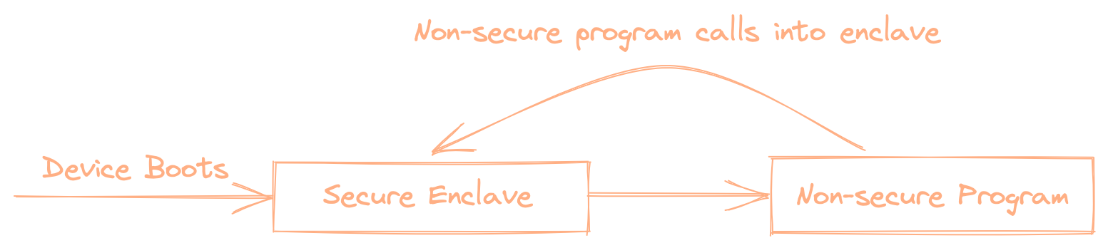 TrustZone-M works a little different to other enclave solutions. In particular when you boot the device, it actually starts in the enclave! In TrustZone, the enclave is essentially a bootloader, which is responsible for initializing the non-secure code. Which at first seems a little backwards, but it is actually key to allowing us to implement all the other enclave features.
I'm going to stop just explaining TrustZone-M now, and actually, have us start coding to help better explain what it is. All the code here is designed to be run on an nRF5340-DK and was compiled on M1 and Intel Macs. You can use other devices, but lots of specifics will be different.
Dependency Hell
First things first, we are going to need to grab a few dependencies.
- ARM GCC Toolchain — This can be installed through Homebrew on macOS, through the ARM website installer, or your local package manager. If you are a Nix addict, you can install the package
gcc-arm-embedded - nRF Connect Command Line Tools
- A recent version of Rust
Ok got all that, good. Now we can start off by creating our first embedded Rust project. Start by running
cargo init tz-getting-started
Now we are going to add a few dependencies to the Cargo.toml file.
cortex-m = "0.7.3"
cortex-m-rt = "0.7"
rtt-target = {version = "0.2.0", features = ["cortex-m"] }
nb = "0.1.2"
nrf5340-app-pac = "0.10.1"
nrf5340-app-hal = { features = ["rt"], git = "<https://github.com/nrf-rs/nrf-hal.git>"  }
As good microcontroller developers, our first goal should be to make an LED turn on. So we will drop into main.rs and put the following. If this seems like a lot already don't worry. I'm going to explain each line, as soon as we get it running.
#![no_main]
#![no_std]

use nrf5340_app_hal as hal;
use nrf5340_app_hal::gpio::Level;

#[panic_handler] // panicking behavior
fn panic(_: &core::panic::PanicInfo) -> ! {
    loop {
        cortex_m::asm::bkpt();
    }
}

#[cortex_m_rt::entry]
fn main() -> ! {
    let p = hal::pac::Peripherals::take().unwrap();
    let pins0 = hal::gpio::p0_s::Parts::new(p.P0_S);
    pins0.p0_28.degrade().into_push_pull_output(Level::Low);
    loop {}
}
Now if you try and build this you will run into the following error (at least on macOS)
LLVM ERROR: Global variable '__INTERRUPTS' has an invalid section specifier '.vector_table.interrupts': mach-o section specifier requires a segment and section separated by a comma.
What did we do wrong? Well, let's break down the error message a little. It says it's coming from LLVM, but it is mainly complaining about Mach-O. That probably means it's a linker error. In particular, it's unhappy that there is a new section called "vector_table.interrupts". Hold onto that name, cause we will dive into what that is later in the article
To fix this issue we have to run cargo build --target thumbv8m.main-none-eabihf. You'll likely not have this target installed already. So you'll need to install it with: rustup target add thumbv8m.main-none-eabihf .
Ok now you have a complete build, but how do we actually run it? Well, the first step is that we need to get the binary into a more comfortable format. We are going to use the fantastic cargo-binutils crate to help us out with this. To install it run
cargo install cargo-binutils
rustup component add llvm-tools-preview
Now you can run
cargo objcopy --target=thumbv8m.main-none-eabihf -- -O ihex blink.hex
This command converts our compiled ELF file into an Intel Hex formatted file, which is commonly accepted by debuggers. Now we can flash that with
nrfjprog --program blink.hex --sectorerase --reset
Next, you'll probably get an error like
ERROR: The operation attempted is unavailable due to readback protection in
ERROR: your device. Please use --recover to unlock the device.
This is caused by some built-in flash protection on the nRF5340. You'll need to "recover" the device, by running nrfjprog --recover and then re-running the above command.
Now you'll probably get yet-another error
Parsing image file.
ERROR: An invalid argument was provided. Use --help for a list of valid
ERROR: arguments.
Like many things in embedded development, this error is indecipherable. If you open blink.hex in your favorite text editor, you'll see that it’s mostly empty.
:00000001FF
If your ELF file has the wrong layout objcopy won't copy any of the data. How do we get the ELF file to have the correct layout? Linker scripts!
Linker scripts are one of those things that I always viewed as a little black magic. Through some means they allow you to modify memory locations, add symbols, and all sorts of other stuff. When it comes down to it though they aren't all that complicated. The linker script lets you give guidance to the linker about how to layout our application. You can define sections that your compiler is looking for like .text, .rodata , and so on. Thankfully the cortex-m-rtcrate does all the heavy lifting for us.
We just need to add the following to .cargo/config.toml
[target.thumbv8m.main-none-eabihf]
linker = "arm-none-eabi-ld"

[target.'cfg(all(target_arch = "arm", target_os = "none"))']
rustflags = [
    "-C", "link-arg=--nmagic",
    "-C", "link-arg=-Tlink.x",
]

[build]
target = "thumbv8m.main-none-eabihf"
This tells the Cargo to use the arm linker, and for the linker to look for the link.x file that cortex-m-rt provides. The link.x file references a file called memory.x , so we need to add that to the root of our crate.
MEMORY
{
    FLASH        : ORIGIN = 0x00000000, LENGTH = 256K
    RAM          : ORIGIN = 0x20000000, LENGTH = 128K
}
Now if you rebuild and flash with
cargo objcopy --target=thumbv8m.main-none-eabihf -- -O ihex blink.hex
nrfjprog --program blink.hex --sectorerase --reset
You should see an LED turn on!
Let's go over quickly what exactly we just did, as it will help us better understand the setup process that will happen when we finally use TrustZone.
Let focus on these two lines
#[cortex_m_rt::entry]
fn main() -> ! {
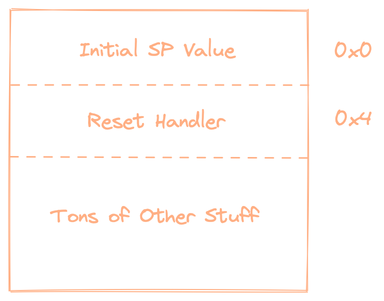
They are deceptive in that it looks like a standard Rust main, with a macro applied to it. But behind the scenes, a couple of key things are taking place. cortex_m_rt setups the vector table for us. The vector table contains the addresses of various exception handlers, interrupt handlers, and importantly for us the reset handler. The reset handler is the first bit of code to run on the device. Inside of that handler cortex_m_rt sets up the stack for Rust and then jumps to our main function.
Another important line is
let pins0 = hal::gpio::p0_s::Parts::new(p.P0_S);
This gets us a reference to the P0 GPIO registers on the nRF5340. You'll notice that we are actually referencing P0_S. The "_S" stands for "secure". When a TrustZone-M enabled device first boots, it is put into secure mode by default. Many devices allow more specific configuration of peripherals. In the case of the nRF5340, it exposes duplicate register blocks for many of its peripherals: one _S (secure), and one _NS (non-secure). _S peripherals can only be used from secure code, whereas _NS peripherals can only be used after they have been enabled.
Jumping into the deep-end
So if we want to use non-secure peripherals, what do we have to do? TrustZone-M, much like SGX, allows us to section off a portion of memory to the secure application and the non-secure application. However, unlike SGX, the processor starts in secure mode and it is our sacred duty to transition the processor to non-secure mode. So we are going to write our own bootloader.
Ok, so how do we do that. First things first, make a copy of the project we have been working on and name it bootloader. Now replace your entire main.rs
#![no_main]
#![no_std]

use rtt_target::{rprintln, rtt_init_print};

    const NON_SECURE_START: u32 = 0x00050000u32;
    const NON_SECURE_SRAM_START: u32 = 0x10000u32;
    const ROM_SIZE: u32 = 0x100000;
    const REGION_SIZE: u32 = 0x4000; // pulled from https://docs.zephyrproject.org/latest/reference/kconfig/CONFIG_NRF_SPU_FLASH_REGION_SIZE.html
    const SRAM_REGION_SIZE: u32 = 0x2000;
    const RAM_SIZE: u32 = 0x80000;

#[panic_handler] // panicking behavior
fn panic(_: &core::panic::PanicInfo) -> ! {
    loop {
        cortex_m::asm::bkpt();
    }
}

#[cortex_m_rt::entry]
fn main() -> ! {
    rtt_init_print!();
    rprintln!("bootloader start");
    unsafe {
        let spu = &*nrf5340_app_pac::SPU_S::ptr();
        for i in 0..(NON_SECURE_START / REGION_SIZE) {
            spu.flashregion[i as usize].perm.write(|w| {
                w.write().enable();
                w.read().enable();
                w.execute().enable();
                w.lock().unlocked();
                w.secattr().secure();
                w
            });
        }

        for i in (NON_SECURE_START / REGION_SIZE)..ROM_SIZE / REGION_SIZE {
            spu.flashregion[i as usize].perm.write(|w| {
                w.write().enable();
                w.read().enable();
                w.execute().enable();
                w.lock().locked();
                w.secattr().non_secure();
                w
            });
        }

        for i in 0..(NON_SECURE_SRAM_START / SRAM_REGION_SIZE) {
            spu.ramregion[i as usize].perm.write(|w| {
                w.write().enable();
                w.read().enable();
                w.execute().enable();
                w.lock().locked();
                w.secattr().secure();
                w
            });
        }

        // set non-secure RAM region
        for i in (NON_SECURE_SRAM_START / SRAM_REGION_SIZE)..(RAM_SIZE / SRAM_REGION_SIZE) {
            spu.ramregion[i as usize].perm.write(|w| {
                w.write().enable();
                w.read().enable();
                w.execute().enable();
                w.lock().locked();
                w.secattr().non_secure();
                w
            });
        }

        // enable GPIO port for NS section
        spu.gpioport[0].perm.write_with_zero(|w| w);

        // enable non-secure for various peripherals
        pass_peripheral_ns(nrf5340_app_pac::P0_NS::PTR);
        pass_peripheral_ns(nrf5340_app_pac::MUTEX_NS::PTR);
        pass_peripheral_ns(nrf5340_app_pac::UARTE0_NS::PTR);
        pass_peripheral_ns(nrf5340_app_pac::TIMER0_NS::PTR);

        //disable SAU so Nordic's SPU can take over
        let sau = &*cortex_m::peripheral::SAU::ptr();
        // For some reason cortex_m doesn't make helper functions public,
        // so here are some magic numbers. This is equivalent to
        // ctrl = 0 # Disable SPU
        // ctrl ~= SAU_CTRL_ALLNS_Msk # make all memory
        sau.ctrl.modify(|mut ctrl| {
            ctrl.0 = ctrl.0 & (!1);
            ctrl.0 = ctrl.0 | (1 << 1);
            ctrl
        });

        let scb = &*cortex_m::peripheral::SCB::ptr();
        let mut aircr = scb.aircr.read() & !(0xFFFF << 16);
        aircr |= 1 << 14; // SCB_AIRCR_PRIS_Msk
        scb.aircr.write((0x05FA << 16) & (0xFFFF << 16) | aircr);

        let mut aircr = scb.aircr.read() & !(0xFFFF << 16);
        aircr |= 1 << 13; // SCB_AIRCR_PRIS_Msk
        scb.aircr.write((0x05FA << 16) & (0xFFFF << 16) | aircr);

        // set VTOR to non-secure vector table
        core::ptr::write_volatile(0xE000ED08 as *mut u32, NON_SECURE_START);
        // the vector table is held at the start of the image
        let ns_vector_table = NON_SECURE_START as *const u32;
        // get address of reset handler, this comes equiv to ns_vector_table[1]
        let ns_reset_vector = *((NON_SECURE_START + 4) as *const u32) & !1;
        rprintln!("found reset vec {:#x}", ns_reset_vector);
        rprintln!("writing msp at: {:#x}", *ns_vector_table);
        // set the MSP (main stack pointer) register to NS
        cortex_m::register::msp::write_ns(*ns_vector_table);
        cortex_m::asm::bx_ns(ns_reset_vector);
        unreachable!()
    }
}

#[inline]
pub fn pass_peripheral_ns<T>(reg_block: *const T) {
    let base_addr = reg_block as u32;
    let id = (base_addr >> 12) as u8;
    unsafe {
        let spu = &*nrf5340_app_pac::SPU_S::ptr();
        spu.periphid[id as usize].perm.write(|w| {
            w.secattr().non_secure().lock().locked();
            w
        });
    }
}
Don't worry if lots of that code doesn't make sense yet, we will go over it in a second.
Let’s go over the code in the bootloader line by line, so we can get a feel for what each one does. I’m going to start with pass_peripheral_ns since it contains many of the patterns and features of other parts of the code base, while being self-contained. The goal of the function is to allow the passed peripheral to be used from non-secure code.
let spu = unsafe { &*nrf5340_app_pac::SPU_S::ptr() };
The nRF5340 has a module called the SPU (System Protection Unit). It is responsible for enforcing various security features, including allowing peripherals to be called from non-secure code. On Cortex-M embedded devices peripherals are exposed through memory-mapped registers. In this case, the nrf5340_app_pac has given us convenient access to the registers. The ptr method gives us a type of *const RegisterBlock so we need to de-reference and borrow to get a borrowed reference.
let base_addr = reg_block as u32;
let id = (base_addr >> 12) as u8;
Each of these peripherals is given an id in the SPU (and through the nRF5340), which happens to be the memory address of the register block bit-shifted right 12 times. There is some indication that this isn't universally true on the nRF5340, but it worked for all the peripherals I've tested with and is pulled straight from Nordic's documentation. So we are gonna roll with it.
spu.periphid[id as usize].perm.write(|w| {
    w.secattr().non_secure().lock().locked();
    w
});
Next, we access the SPU register associated with this peripheral and set it to non-secure mode. This step looks like the easiest because the brilliant svd2rust generated code has given us a nice builder for it. In actuality, there is a hellish amount of masking and bit-shifting happening here that we don't have to look at.
spu.gpioport[0].perm.write_with_zero(|w| w);
The SPU allows you to control the exact GPIO pins that are exposed to non-secure code. This would allow you to connect multiple peripherals to the same GPIO port, but not expose all of them. In this case, if we write 0 to GPIO register it marks all pins as non-secure.
Now let’s go back to the top, and review the rest of the bootloaders code.
const NON_SECURE_START: u32 = 0x00050000u32;
const NON_SECURE_SRAM_START: u32 = 0x10000u32;
const ROM_SIZE: u32 = 0x100000;
const REGION_SIZE: u32 = 0x4000; // pulled from <https://docs.zephyrproject.org/latest/reference/kconfig/CONFIG_NRF_SPU_FLASH_REGION_SIZE.html>
const SRAM_REGION_SIZE: u32 = 0x2000;
const RAM_SIZE: u32 = 0x80000;
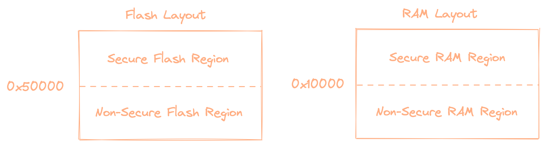
We first set up some constants for use later in the program. These define the various memory regions. Flash and ram are both split into a secure region and a non-secure region.
 Next we have 4 blocks that all kind of look the same
for i in 0..(NON_SECURE_START / REGION_SIZE) {
    spu.flashregion[i as usize].perm.write(|w| {
        w.write().enable();
        w.read().enable();
        w.execute().enable();
        w.lock().unlocked();
        w.secattr().secure();
        w
    });
}
Each of these blocks does the same basic thing. It sets attributes of a certain memory region. In the above instance it marks our secure region as secure, writable, and executable. The register allows you to set the attributes for 64KB blocks. We assume that our memory region values are aligned to 64KB, and so we can loop through them.
let sau = &*cortex_m::peripheral::SAU::ptr();
// For some reason cortex_m doesn't make helper functions public,
// so here are some magic numbers. This is equivalent to
// ctrl = 0 # Disable SPU
// ctrl ~= SAU_CTRL_ALLNS_Msk # make all memory
sau.ctrl.modify(|mut ctrl| {
    ctrl.0 = ctrl.0 & (!1);
    ctrl.0 = ctrl.0 | (1 << 1);
    ctrl
});
This block references a component we haven't talked about yet, the SAU or Secure Attribution Unit. This is an internal unit to TrustZone-M enabled cores. It has a lot of overlap with Nordic's SPU but is often less configurable for a chip’s specific security needs. This block of code disables the SAU, so the SPU can take over. Why are there two different components of the CPU with almost identical characteristics?
I have no clue, but at least we can more or less ignore the SAU.
let scb = &*cortex_m::peripheral::SCB::ptr();
let mut aircr = scb.aircr.read() & !(0xFFFF << 16);
aircr |= 1 << 14; // SCB_AIRCR_PRIS_Msk
scb.aircr.write((0x05FA << 16) & (0xFFFF << 16) | aircr);

let mut aircr = scb.aircr.read() & !(0xFFFF << 16);
aircr |= 1 << 13; // SCB_AIRCR_BFHFNMINS_Msk
scb.aircr.write((0x05FA << 16) & (0xFFFF << 16) | aircr);
Another block of code, another register block. This time it's the SCB or System Control Block. Which is responsible for configuring interrupt and exception handling. In particular, we are setting the SCB_AIRCR_PRIS_Msk and SCB_AIRCR_BFHFNMINS_Msk bits. SCB_AIRCR_PRIS_Msk prioritizes secure exception over non-secure exception. So if you register two handlers, one for the secure-realm and one for the non-secure realm, the secure handler will be called instead of the non-secure handler. In Cortex-M certain exceptions "bank" the previous register values before they are called. Setting SCB_AIRCR_BFHFNMINS_Msk tells the CPU to send non-banked exceptions to the non-secure element.
core::ptr::write_volatile(0xE000ED08 as *mut u32, NON_SECURE_START);
This line sets the VTOR to the start of the non-secure vector table. Now you might ask, "what is a VTOR and why do we need to set it?" The VTOR, Vector Table Offset Register, tells the CPU where to find the vector table to use for interrupt and exception handlers.
let ns_vector_table = NON_SECURE_START as *const u32;
Ok, now we cast the address of the non-secure start to a pointer. This is so we can later use the start of the vector table to get the address of the MSP (Main Stack Pointer); more on this later.
let ns_reset_vector = *((NON_SECURE_START + 4) as *const u32) & !1;
This line is a little funky and possibly hard to parse on its own. NON_SECURE_START + 4 pushes us 4 bytes ahead in the vector table. We then cast that entry as a pointer, and dereference it. That gives us the address of the reset-handler, but then we do something a little strange to it. What does & !1 do? It effectively flips the first bit of the address.
Why does that work at all, and why would we want to do that? Well, my child, come here and listen to a tale of two instruct sets and program counters. You might be tempted to think that there is only one 32 bit ARM instruction set, but you'd be wrong. In fact, there are two: A32 and T32. You may have noticed that the target we used to compile the Rust program is called thumbv8m, a reference to the fact that pre-ARMV8-M T32 was called Thumb (or possibly Thumb2, it’s all very poorly named). Back in ye olden days, Thumb was a 16-bit instruction set. Nowadays Thumb has grown into T32, which is a mix of 16bit and 32-bit instructions. Either a 16 or 32-bit instruction set will have all instructions aligned at a power of two. Meaning that the least significant bit should always be 0. Many ARM chips support switching between A32 and T32, and to do this they have you flip the least significant bit (LSB). If you wanted a T32 jump you set the LSB to 1. But Cortex-M only supports Thumb, so there is a full extra bit of the PC that can be used to encode a flag. ARM, in their cleverness, chose to use the LSB to denote transitions between secure and non-secure code. But since 1 was the default value for T32, you set the flag to 0 to denote an intentional jump to non-secure code. It’s a little confusing but is really a quite clever way to denote the jump.
cortex_m::register::msp::write_ns(*ns_vector_table);
Next, we have to tell the processor where to find the stack, by writing to the MSP (Main Stack Pointer) register. As shown above, the initial stack pointer is at the first position in the vector table, and so we de-reference here.
cortex_m::asm::bx_ns(ns_reset_vector);
Ok, now we actually jump to the instruction. BX is an ARM instruction that jumps to a particular pointer. It also does some other stuff related to return handling we won’t cover her. The astute among you will notice that we call BXNS here instead of plain BX. That is because we are making a call into non-secure code, rather than a normal jump. I suspect they have differentiated BX and BXNS because they wanted to throw a fault when code would try to run A32 instructions on a T32 only processor. So it wasn’t enough to just use the LSB as a flag for secure jumps. Why then do you have a flag set on the pointer I don’t know.
unreachable!()
We can safely mark this as unreachable, as bx_ns is guaranteed to either jump or fault.
Now that we have written the bootloader, lets test it out. You’ll need to modify the original tz-getting-startedmain.rsline 17 to read:
let pins0 = hal::gpio::p0::Parts::new(p.P0_NS);
Next replace the entire memory.x file in tx-getting-started
with the following
MEMORY
{
    FLASH        : ORIGIN = 0x00050000, LENGTH = 767K
    RAM          : ORIGIN = 0x20020000, LENGTH = 128K
}
This will tell the linker to place our non-secure image starting at 0x50000. Now we have made all the necessary changes, we can flash both the bootloader and non-secure program as we did above.
We need to go deeper
So far we have successfully shown how to move from secure code to non-secure code, and boy-oh-boy did it require a lot of steps. But that ability alone is not particularly useful. What we really want is the three features we discussed above: sealing, attestation, and memory protection. We already have memory protection of the secure code from the non-secure code provided by TrustZone. Sealing and attestation will be slightly more difficult, as TrustZone doesn’t provide it for us. As discussed for Intel SGX, a key component of attestation is signing the report using an authorized key. Most ARM TrustZone compatible SoCs have an additional feature called a KMU (Key Management Unit). That is a peripheral responsible for storing and using cryptographic keys. Since we can partition peripherals for secure only use, we can enforce that only the CryptoCell is accessed by the secure partition. CryptoCell’s contain a Hardware Unique Key (HUK) that can be used to sign and derive other keys. We can use that key to sign the attestation report. But how do we guarantee that our device is running trusted software in the secure enclave? We can do that through the use of yet more cryptography. We designate a manufacturer-specific key and use that to sign our HUK public key. We only sign the HUK, after the device has been flashed. This allows us to pass on the signature to any interested party, to attest that we are a legitimate enclave. Of course, someone could come and overwrite our secure code. To prevent that we change two special registers called SECUREAPPROTECT and ERASEPROTECT. Together these allow you to prevent external parties from overwriting the secure portion of memory. Our bootloader can now generate attestation reports about itself or the flash that it has booted into. Sealing takes a similar route to attestation. We can use the HUK to encrypt any data we please.
The call of the enclave
For embedded devices, there are two primary goals for an enclave. One is to separate simple high-security code from more complex difficult to verify code. If there, happens to be a vulnerability in the more complex code, the blast radius will be limited to the untrusted code. The other is to provide a mechanism for updating the firmware of the device. Both cases require some communication from the non-secure firmware.
So, now how do we call a secure function. You might assume that you can just get the address of a secure function, and cast a function to it. But if you try that you’ll find your code crashing. Instead, we have to do a special ceremony to tell TrustZone that it’s OK to transition from non-secure to secure. In assembly that dance looks like this:
SG
BW __secure_function
BW we already saw above, is a branching instruction in the ARM instruction set. SG is the “secure gateway” instruction; it marks a non-secure to secure transition for the CPU. If you run this code it would still fault though, since we need to place these “veneers” in a special region called NSC, non-secure callable code. Before we do that we are going to need to make some changes to our project. In your bootloader project directory, we are going to create a new file called memory.ld.
MEMORY
{
    FLASH        : ORIGIN = 0x00000000, LENGTH = 256K
    SHARED_RAM   : ORIGIN = 0x20010000, LENGTH = 64K
    RAM          : ORIGIN = 0x20000000, LENGTH = 128K
}

#define CONFIG_NRF_SPU_FLASH_REGION_SIZE 0x4000

#define __NSC_ALIGN (ALIGN(CONFIG_NRF_SPU_FLASH_REGION_SIZE)  - MAX(32, (1 << LOG2CEIL(__sg_size))))
#define NSC_ALIGN . =  (__NSC_ALIGN + ((ABSOLUTE(.) > __NSC_ALIGN)  ? CONFIG_NRF_SPU_FLASH_REGION_SIZE : 0))
#define NSC_ALIGN_END . = ALIGN(CONFIG_NRF_SPU_FLASH_REGION_SIZE)

SECTIONS
{
  .gnu.sgstubs :
  {
    NSC_ALIGN;
    __sg_start = .;
    } > FLASH
    __sg_end = .;
    __sg_size = __sg_end - __sg_start;
    NSC_ALIGN_END;
    __nsc_size = . - __sg_start;
} INSERT AFTER .rodata;

#define NRF_SG_START (__sg_start % CONFIG_NRF_SPU_FLASH_REGION_SIZE)
#define NRF_SG_SIZE (CONFIG_NRF_SPU_FLASH_REGION_SIZE - NRF_SG_START)
ASSERT((__sg_size == 0)
    || (((1 << LOG2CEIL(NRF_SG_SIZE)) == NRF_SG_SIZE) /* Pow of 2 */
        && (NRF_SG_SIZE >= 32)
        && (NRF_SG_SIZE <= 4096)),
    "The Non-Secure Callable region size must be a power of 2 \\
between 32 and 4096 bytes.")
This file contains a new linker script, with some helpful macros. You’ll notice that we have added a new section called .gnu.sgstubs. In that section, the linker is going to place those veneers we discussed earlier. We also have a good amount of math here to align sgstubs to the end of a 64KB region. This sort of alignment is only a requirement on Nordic processors, but since that is all we are supporting right now we don’t include any conditional behavior.
When I started this work I had assumed linker scripts could include C macros by default, since I had seen it used so often in C projects. It turns out that is not the case. Instead, most C build-systems run the C pre-processor on linker scripts beforehand. Since this is Rust we are going to trigger that pre-processor in our build.rs file. First, add the following dependency to the Cargo.toml file.
[build-dependencies]
gpp = "0.6"
gpp is a Rust crate that provides a pre-processor with a similar syntax to C’s pre-processor. It isn’t identical, but for what we are doing it is perfectly adequate. Next, we are going to add a build.rs script to process our file
use std::env;
use std::fs::File;
use std::io::Write;
use std::path::PathBuf;

fn main() {
    let out = &PathBuf::from(env::var_os("OUT_DIR").unwrap());
    let memory_x = gpp::process_str(include_str!("memory.ld"), &mut gpp::Context::new()).unwrap();
    File::create(out.join("memory.x"))
        .unwrap()
        .write_all(memory_x.as_bytes())
        .unwrap();
    println!("cargo:rustc-link-search={}", out.display());
    println!("cargo:rerun-if-changed=memory.ld");
}
Now we have set up the correct linker sections for our veneers, but now we need the compiler to actually make them. For that, we will need to use a nightly Rust feature called cmse_nonsecure_entry. Since it is a nightly feature we will have to tell Cargo to use the nightly toolchain. The best way to do that is to add a file called rust-toolchain.toml to the root of the bootloader crate.
[toolchain]
channel = "nightly-2021-10-21"
components = [ "rustfmt", "rustc-dev" ]
targets = [ "thumbv8m.main-none-eabihf" ]
profile = "minimal"
Now in our main.rs we are going to add #![feature(cmse_nonsecure_entry)] to the top of the file, and add the following function call to the bottom
#[no_mangle]
#[cmse_nonsecure_entry]
pub extern "C" fn secure_test_fn(input: u32) -> u32 {
    input + 6
}
That isn’t the most interesting function, but it will showcase that we can make a function call into non-secure code. By adding #[cmse_nonsecure_entry] we are telling the compiler to generate a veneer for the function. #[no_mangle] tells the compiler not to “mangle” the name of the function, as Rust typically modifies function names to ensure uniqueness.
Now if you run cargo objdump -- -d you’ll see our veneers generated by the compiler, and place them in the correct section:
Disassembly of section .gnu.sgstubs:

00004480 <secure_test_fn>:
    4480: 7f e9 7f e9  	sg
    4484: fb f7 02 bf  	b.w	0x28c <__acle_se_secure_test_fn> @ imm = #-16892
We still aren’t done though, since we need to mark the sgstubs section as NSC. Start by adding the following just above main
// values imported from linker script
extern "C" {
    static __sg_start: u8;
    static __sg_end: u8;
    static __sg_size: u8;
}
This allows us to reference some symbols we defined in our new linker script. Next just after we set the RAM regions, we will add the following
let sg_start =  &__sg_start as *const u8 as u32;
let nsc_size = REGION_SIZE - (sg_start % REGION_SIZE);
let size_reg = (31 - nsc_size.leading_zeros()) - 4;
let region_reg = (sg_start as u32 / REGION_SIZE) & 0x3F; // x << SPU_FLASHNSC_REGION_REGION_Pos & SPU_FLASHNSC_REGION_REGION_Msk
spu.flashnsc[0].size.write(|w| {
    w.bits(size_reg);
    w
});
spu.flashnsc[0].region.write(|w| {
    w.bits(region_reg);
    w
});
We set the NSC region based on a flash region and a size. The size is an offset from the end of the region. At this point, we are almost ready to call code NSC, but first, we need to make our non-secure code aware of the functions and veneers. To do that the linker can generate an implib, an object that contains the addresses and symbols of secure veneers. We can then reference that implib in our non-secure code to call the functions.
Generating the library is fairly simple, we just need to add some flags to the linker. We can do that using the build script
println!("cargo:rustc-link-arg=--cmse-implib");
println!(
    "cargo:rustc-link-arg=--out-implib={}",
    out.join("libnsclib.a").display()
);
This will create the output library in the output directory for the bootloader. Run a quick build, and then run find . -name 'libnsclib.a'. You can then copy that file to the tz-getting-started project root. In main.rs we’ll add a few lines to reference the secure functions.
#[link(name = "nsclib")]
extern "C" {
    pub fn secure_test_fn(input: u32) -> u32;
}
Now we can actually call the secure function. Add this somewhere above loop {}
let res = unsafe { secure_test_fn(10) };
rprintln!("res is {:?}", res);
Before building, we need to tell Rust where to find our new implib. Put this in a new build.rs :
use std::env;

fn main() {
    println!(
        "cargo:rustc-link-search=native={}", env!("CARGO_MANIFEST_DIR")
    );
}
Make sure to add the import use rtt_target::rprintln;
Now you can program both the new bootloader and tz-getting-started. It’s important to update the implib every time you change the bootloader, as that changes the memory locations of the secure veneers.
You’ll notice we are using something called rprintln! that is a special macro that prints data to the debugger using RTT (Real-Time Transfer). You can view the logs using the Segger JLINKRTTViewer. Simply open the app, and select the NRF5340_XXAA_APP as the target device. Now you should see the following output
non secure start
res is 16
Eureka! or maybe not. This might feel a bit anti-climactic, but I assure you this feature is the core of all the other secure-enclave features we can build. Now that we can call into the enclave, we can do all sorts of trusted computation. We could implement a secure firmware updating mechanism. Or use the enclave for a payments solution (a-la Apple Pay).
In Conclusion
So far we have successfully created a new bootloader/enclave using TrustZone-M and Rust. We have shown how to expose peripherals, transition to a non-secure program, and call the secure-enclave from non-secure code. But, the keen-eyed among you will notice that we are still missing two fairly key features of enclaves, sealing and attestation. I may write a follow-up post that covers those in more detail if there is interest. Even if we don’t write another blog post, we will be open-sourcing various support code to write attestation and sealing code using TrustZone, CryptoCell, and the Nordic KMU (management unit).
I, along with the rest of my team, will be working on a new library that will act as a toolkit for building bootloaders and enclaves in Rust. It’s called Frumsceaft, which in old English means the origin or creation. I hope to add support for more microcontrollers, in particular TrustZone compatible members of the SM32 series are next up. We will be adding support for sealing and attestation, in addition to more advanced bootloader features like image verification and firmware updates.
After publishing this post ARM created some real documentation for TrustZone-M on Rust